Electric current is the rate of flow of charge
In metallic conductors the charge carriers are electrons which move from the negative terminal to the positive terminal. This should not be confused with current, which moves from the positive terminal towards the negative terminal, also known as conventional current.
We can also define current as:

Where I is current (amps), Q is charge (coulombs) and t is time (seconds)
This can be arranged to:

Potential Difference is work done per unit charge
A charge gains energy when it passes through a cell. It releases the gained energy as it passes through components in a circuit, and a potential difference exists across the component.

Where V is voltage (volts), q is charge (coulombs) and W is energy (joules)
Charge faces opposition when it flows around a circuit. This is called resistance and it is measured in ohms (Ω). The potential difference needed to make a current flow in a circuit depends on the resistance in the circuit. The bigger the resistance, the more potential difference is required to make a certain current flow.
We can define this as:

Where R is resistance (ohms), V is voltage (volts), and I is current (amps)
Current Voltage Characteristics
We can measure current using an ammeter and voltage with a voltmeter in order to obtain information about the following characteristics.

The circuit symbol for an ammeter

The circuit symbol for a voltmeter
Ohmic conductors are components which follow Ohm's law, and show that voltage is directly proportional to current. These display a straight line on V-I graphs.
Examples include: all metals

The shape of a semiconductor diode depends on the direction in which the current is flowing.
When the diode is facing forward, there is a large resistance between 0 and 0.7V, however the resistance decreases quickly between 0.7 and 1V, and a large current flows, making the graph increase sharply.
On the other hand, when the diode is reversed and is facing backwards, there is high resistance, and so an extremely small amount of current flows. At the breakdown voltage, generally between 50 and 500V, a large current flows, however most diodes break down due to a high heating effect at such a high current.

Filament lamps do not follow Ohm's law. They show that current is proportional to voltage at small readings, however they start to curve as the current increases in both directions. This is due to the heating effect when a high current flows through - a high temperature increases the resistance of the filament in the lamp, and so there is a decrease in current.

Ohm's law states that the current in a conductor is directly proportional to the potential difference across it, provided that the temperature and other physical conditions remain the same.
Resistivity
Two factors which affect the resistance of a conductor are its length and it's cross sectional area
Resistance is directly proportional to length, and indirectly proportional to the cross sectional area - if you double the length of the wire, the resistance doubles. If you double the area, the resistance will half.
The resistivity of a wire is defined as

where rho is resistivity (ohm metres), R is resistance (ohms), A is the cross sectional area (metres squared), and L is the length of the wire (metres).
Metal wires and resistors have delocalised electrons that move through the metal when a potential difference is applied, causing a current to flow. The metal also has vibrating positive ions. Electrons collide with these ions, causing the ion to have resistance to the current.

As the temperature of the wire increases, the positive ions and electrons will both absorb the heat energy, causing the both to vibrate more. This means that there is a higher number of collisions between electrons and ions, and thus resistance increases.

However, in the case of a thermistor, the resistance decreases as the temperature increases.
Small increases in temperature produce large changes in resistance of the thermistor. The thermistor is made from semiconductor material and therefore has few free electrons to produce a current. As the temperature of the thermistor increases, the thermal energy is enough to release further electrons from the ions to make the material conductive, and thus resistance decreases.
Uses for a thermistor include: temperature sensors eg. fire alarms

The circuit symbol for a thermistor
If the temperature of a conductor is decreased until it reaches absolute zero (0K or -273 degrees celsius) the electrical resistance becomes non negligible. The conductor is then rendered as a superconductor - since it's resistivity has become zero, an electric current can pass through without transferring any energy to the conductor. The temperature at which the material becomes a superconductor is know as the critical temperature.

Circuits
In order for a current to exist, a potential difference must exist. Potential difference is the amount of electrical energy that must be transferred to the charge and is measured in joules per coulomb or volts.
The charge releases the gained energy as it passes through components in a circuit. All the potential energy lost by the charge is generally changed into heat.
Energy is measured in Watts
From formulas, we can deduce that:

where W is work done/energy (watts), V is voltage (volts), I is current (amps) and t is time (seconds)
Power is the rate of change of energy, and is measured in joules per second or Watts. It can be defined as:

We can then substitute V= IR into the equation above and arrive at alternative formulas.

In all circuits, electric charge is conserved - all the charge which arrives at a point must leave it. Current is the flow of charge.
At any point in a circuit where conductors join, the total current towards the point must equal the total current flowing away from the point.

This means that in the circuit above, the current in question is 2A.
We can deduce this from 3 - 0.67 - 0.33 = 2A
In circuits, energy differences are expressed as potential differences and measured in volts. Energy is always conserved in all circuits.
The algebraic sum of potential differences around a closed circuit is always zero.

For a series circuit, this is pretty simple - add up all the values
For components in parallel, the voltage is exactly the same over each "arm" of the circuit
The total resistance in a series circuit is just the sum of resistance.
The total resistance in a parallel circuit can be calculated by the following equation:

Potential Dividers
A potential divider splits up the potential difference from a source. This can be done using two or more resistors in series. In this case, the potential difference across the output terminals varies according to the ratio of the resistances in series.

We can then deduce that:
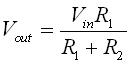
Uses for a potential divider include: an audio volume control
We can also incorporate light and temperature sensors in order to vary the output voltage depending upon the conditions.
A light sensor (LDR) has a low resistance in bright light and a high resistance in darkness. Using a potential divider, the output voltage can be made to change with light intensity.
As the light gets dimmer the resistance of the LDR gets higher, the ratio of resistances changes, and so does the voltage ratio.
A temperature sensor (thermistor) has a low resistance when hot and a high resistance when cold. Using a potential divider can vary the output voltage with temperature changes.
As the temperature decreases, the resistance of the thermistor increases and the voltage ratios changes such that the output voltage decreases
Electromotive Force and Internal Resistance
We can define the electromotive force (EMF) as the potential difference across the source when no current flows, and is the energy per coulomb produced by the source. We can also define it by the equation:

Where V is EMF (volts), W is energy (watts), and Q is charge (coulombs)
(EMF is normally given an epsilon as a symbol rather than voltage)
The materials inside a cell offer resistance to the flow of current. This is known as the internal resistance of the cell, and is measured in ohms.
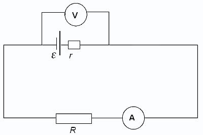
When no current flows in the circuit, then the EMF = the potential difference across the cell
When current flows in the circuit there is a potential difference across R, and a potential difference across r.
Both energy and charge are conserved in the circuit.
The current should be the same in any part of the circuit.
We can then deduce that:
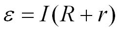
Car batteries require low internal resistance in order to have as much current in order to start up the car - internal resistance limits the amount of current.
Alternating Currents
Root mean square: since the alternating current or potential difference is continually changing in value it is impossible to assign a fixed value over a number of cycles. The root mean square current produces the same heating effect in a resistor as the equivalent direct current, ie. the Irms produces the same heating effect as Id.c.
The peak value of an a.c. current or potential difference is the maximum displacement from the zero line in either direction and is labelled either I0 or V0 respectively on the graph.
In order to convert peak values to rms values, the following equation can be used:
The peak to peak value of an ac current or pd is the maximum displacement across both directions and is labelled either Ipp or Vpp respectively on a graph.
The time period of an a.c. current or pd is the time taken for one complete cycle. The unit is seconds or ms.
The frequency of an ac current or pd is the number of complete cycles per second. The unit is Hz.

Oscilloscope

An oscilloscope is used to display waveforms.
It can measure a.c. and d.c. current, small time intervals and frequencies of alternating currents and voltages.
Best ias coaching in bangalore
ReplyDelete.www.globalias.in